Please select any photo in the galleries for a larger version and descriptive caption.
In November 2016, the massive New Safe Confinement arch slid over Unit 4 of the Chernobyl Nuclear Power Plant, and the old “Sarcophagus” that had defined the appearance of the damaged unit for 30 years receded from view. Over the last three years, the iconic ventilation chimney shared by Units 3 and 4 has been disassembled as well, and now rests in pieces in various places (including the deck of No. 5 turbogenerator). Inside the unit, work continues to finish the Perimeter Closure Project–the effort to hermetically seal off the east and west boundaries of the New Safe Confinement from the rest of the power plant. Floor by floor, barriers are going up. The memorial to Valery Khodemchuk, the first victim of the 1986 accident whose remains have never been recovered, has been removed from its old location at the northwest end of the chemical treatment and ventilation block, and will be reinstalled somewhere else once the project is finished. The photos in the second gallery show the state of the Arch and the Local Zone around Unit 4 only several days before the Arch began its movement, and are certainly among the last photos of the old Unit 4 exterior we have come to know and love.
Stanislav Shekstelo, an employee of the Chernobyl Nuclear Power Plant, contemplates the remains of the Unit 4 control room in November 2016. The wall at left is not original, and the last bench of A Desk and T Desk have been removed to allow the wall to be installed through the control room. Behind the wall is a corridor to allow worker movement. The original “gold corridor” that runs the length of the deaerator building is blocked in this area by the supports for the “Mammoth Beam” in the Sarcophagus.
Unit 4’s reactor cartogram displays behind A Desk (the reactor control engineer’s position) at the east end of the Unit 4 control room. Only a few of the ~200 control rod servoindicators remain in the panel, the others having been scavenged for other units and / or souvenirs.
Servoindicator for a control rod in the Unit 4 control room, Chernobyl Nuclear Power Plant, measuring rod insertion depth from 0 to 8 meters. The reading is no longer meaningful. The descending main control rod in Channel 40-37 would have become stuck at about 2m before the core disintegrated.
Slot for No. 8 turbogenerator’s tachometer on T Desk, the turbine control engineer’s position, Chernobyl Nuclear Power Plant. The 1986 accident took place in the context of an inertial run-down experiment on TG-8. A thick coating of pink polymer designed to trap contamination now lies over everything in the Unit 4 control room.
Annunciator lamps for Unit 4’s main circulation pumps, covered in contamination-immobilizing polymer.
Turbogenerator No. 8’s electrical output, from 0-600 MWe. The normal value was 500 MWe at full power. The accident of April 26, 1986 occurred in the context of an experiment on TG-8.
A pancake Geiger counter measures 33 kCPM on the balance-of-plant console (P Desk) in the Unit 4 control room.
Switch on A Desk (the reactor control engineer’s position) for the Unit 4 reactor’s automatic power regulators. The power regulators derive signal from lateral ionization chambers and are used to manage control rod movement under high-power operating conditions. The chain of events leading directly to the accident began with the automatic regulators, which stopped regulating power for some indeterminate reason at 12:30AM on the night of the accident. The operators failed to maintain power with the AR systems, leading to xenon poisoning and the unfortunate conditions for reactor runaway later on.
Slots for the reactor period monitors in Unit 4 control room at Chernobyl. These monitors probably derived their signal from the lateral ionization chambers, and would have read “0 seconds” for a brief, hair-raising moment on April 26, 1986.
A hot-spot warning is stenciled on the wall that now terminates the west end of the +10m deaerator corridor at Axis 53. The Fluke 451B ion chamber measures a respectable 22 mR/h here.
The original deaerator corridor on +10m outside the Unit 4 control room is rarely seen by visitors to the control room, but we had to use it because of work on the Perimeter Closure Project. The reserve control room to Unit 4 is behind the wall on the right, shielded with heavy lead plate. It looked directly out on the vast heap of radioactive debris from the reactor building. Some original linoleum flooring is also visible.
Looking east now, toward the barrier across the +10m deaerator hallway at Axis 53. Behind the wall are supports for the “Mammoth Beam” in the Sarcophagus. The lead paneling at left provides shielding from radiation shining into the plant from outside, via the Unit 4 reserve control room.
The G110/2 stairway at the end of the deaerator building in Unit 4 is in pretty ragged shape, and has been painted with some kind of immobilizing polymer that is pink in color. We are on our way to the Unit 4 control room via a somewhat unusual route on the +16.4m level.
Blast-resistant door leading to one of the steam and feedwater piping compartments below Unit 4’s deaerators on +16.4m elevation. Like all of Unit 4’s primary cooling circuit, it is probably quite contaminated.
Dating from Unit 4’s operational days–as attested by the overlying stratum of pink anti-contamination polymer–is a poster advising about safe welding practices.
The short western hall at the end of the Unit 4 deaerator building was once a “place for smoking”, per the red signage. A new sign has been posted, instructing workers that “smoking in the Object Shelter is PROHIBITED!” (Clearly the prohibition is widely ridiculed, as cigarette butts are everywhere in the Unit 4 control room.) Closer inspection of the sign reveals sarcastic additions, including a “penalty-100 Hryvnia” (about $5) modified to read “$1000000.”
I was honored to have Bionerd along for this trip, and her video record of the visit inside Unit 4 is on YouTube here:
Finally, here is a gallery showing the Arch of the New Safe Confinement and some of the “Local Zone” surrounding Unit 4.
The New Safe Confinement Arch at Chernobyl, only days away from its highly-anticipated move over the damaged Unit 4. PHOTO CREDIT: LUCAS HIXSON
American-made overhead cranes in the New Safe Confinement arch. The cranes will be used for various purposes relating to the study and deconstruction of Unit 4.
Workers in the “Local Zone” surrounding Unit 4 rush to finish the New Safe Confinement Technological Building, Perimeter Closure in the turbine hall, and other projects so that the Arch can be moved before the onset of bitter Ukrainian winter weather. Note that the ventilation stack visible on V Block is not the original, but a much smaller, offset stack that will not interfere with the New Safe Confinement.
Unit 4 is scarcely recognizable from the west, with the technological building of the New Safe Confinement nearing completion (left). The old western counterforce wall that keeps the Sarcophagus from collapsing is behind it. The striped ventilation chimney is a diminutive, offset version of the original. About the only original plant structure visible here is the western end of the deaerator building.
The Arch is designed to slide on rails. This is the southern rail. A lead-sheet shield for workers, at left, reduces the ambient dose rate by about a factor of 4.
One of hundreds of stray dogs on the Chernobyl Power Plant site. This one, however, is on the dirty side of the clean line in the 1430 Change Facility, and I doubt it has been taught to use the contamination monitors visible at left.
A stray dog, one of hundreds that roam the grounds of the Chernobyl Nuclear Power Plant, enjoys the meager nourishment of a radioactive boot heel inside the hot entrance to the 1430 Change Facility. In the foreground is a visitor with a jacket labeled “OU” (“Object Shelter”).
Please select any photo in the galleries for a larger version and descriptive caption.
The reactor hall and control room of Unit 2 at the Chernobyl Nuclear Power Plant are documented in these photo galleries and companion video.
Room 612/2 (Central Hall); Room 804/2 (Refueling Machine Control Room)
The RBMK reactor design features an ability for online refueling: withdrawal and insertion of fuel bundles while the reactor is at power. The charge face with its 2000-some channel covers is sited above the reactor within a massive “central hall” that is built like a hot cell, with concrete entryway mazes and leaded-glass windows for refueling operators. The dominant piece of equipment is, of course, the crane-mounted RZM (refueling machine). Also in the central hall are two spent-fuel basins, fresh fuel and instrumentation storage hangers, and metal plate covers for accessing the upper steamwater pipelines from the reactor and the peripheral ionization chambers. Unit 1 and 2’s central halls are on the +20.2m elevation, typical of first-generation RBMK plants, while the later Unit 3 and 4 central halls are on +35.5m. The chief reason for this is the introduction of a steam-suppressing pool and “Accident Localization System” below the reactor in the later design. Unit 2 has been offline since a turbine hall fire in 1991, and is defueled and dry (all spent fuel is in the ISF-1 facility). The spent fuel pools in the reactor hall are also dry, but are currently being used to store fuel support stringers. Measured exposure rates in the reactor hall range from surprisingly low (3 mR/h on uncovered fuel channels on the “pyatak” or reactor lid) to surprisingly high (2 R/h close to a point source-maybe a fuel flea?-on a fuel stringer). Like other RBMK reactors, including Unit 3 at Chernobyl, ChNPP-2 participated in transmutation doping of silicon for the Soviet semiconductor industry. A single channel ordinarily used for the control and protection system was assigned for this application.
Central Hall of Unit 2, ChNPP, looking south from the fresh fuel storage area. In the distance is the refueling machine and the circular reactor lid. In the foreground is a round portal in the floor for transferring fuel in casks out of the reactor building and onto a rail car beneath.
On the Unit 2 reactor lid, there is some streaming gamma radiation from the empty fuel channels. The exposure rate amounts to about 3.3 mR/h. Note the heavy removable steel blocks used to protect the channels.
2 R/h (yes, that’s two roentgens per hour!) from a local source, suspected of being a fuel flea, on one of the used fuel stringers in the spent fuel storage pool of Unit 2 reactor at ChNPP. Good times.
The crane-mounted RZM (fuel loading and unloading machine) in Unit 2 at ChNPP. Notice the person at the bottom for scale! The lead-glass window to the operator’s room is seen on the wall at right.
This is the reactor lid for Unit 2, Chernobyl Nuclear Power Plant. Metal blocks protect the upper penetrations for some 2000 channels through the graphite moderator of the reactor. The colored lids house electric control-rod drive mechanisms and in-core instruments, while the unpainted ones cover fuel channels and one special channel used to irradiate silicon. To the side of the reactor lid are smaller covers for the upper steamwater pipelines and the lateral ionization chambers.
Upper stringers for fuel bundles in the Unit 2 reactor hall. These pieces have a pin in the foreground for coupling to the RZM machine. At the far end is a spiral geometry designed to help shield streaming neutrons. Two fuel bundles, each about three meters long, would have been attached at the far ends for insertion into the reactor core.
Visitors prepare to enter the Central Hall of Unit 2 at Chernobyl, from the 607/2 anteroom on +20.2m. The Central Hall is a fuel handling area, and consequently has some loose radiological contamination.
Visitors prepare to enter the Central Hall of Unit 2 at Chernobyl from the 607/2 anteroom on +20.2m.
Electrical panels for the RZM refueling machine in the operator’s booth, Room 804/2. PHOTO CREDIT: LUCAS HIXSON
View through the RZM operator’s lead-glass window into the Central Hall, Unit 2, Chernobyl Nuclear Power Plant. PHOTO CREDIT: LUCAS HIXSON
Unit 2 reactor building, Chernobyl Nuclear Power Plant, +20.2m elevation
Video (via YouTube)
Room G364/2 (Unit 2 Control Room)
The control room, like all others at RBMK plants, is situated nominally at +10m elevation in the “deaerator stack” abutting the turbine hall. The tray-type deaerators themselves, and reactor steam and feedwater piping, are in compartments directly above the control rooms, leading to some interesting hypothetical accident scenarios whereby radioactive water might invade the control rooms from above. At ChNPP, the Unit 2 control room has a notable radiation “hot spot” above T Desk at the west end, possibly due to contamination in the steamwater piping compartment upstairs.
A visitor stands behind A Desk (reactor control engineer’s position) in the Unit 2 control room, ChNPP. On the panel behind him is a reactor core cartogram with lamps for each of the ~1700 fuel channels (white) and ~300 other channels for control rods and instrumentation. The lamps were used to indicate various parameters or activities in the individual channels. On the right is another cartogram with servoindicators displaying the position of control and protection rods in the reactor. PHOTO CREDIT: LUCAS HIXSON
Visitors enter Unit Control Room II, Chernobyl Nuclear Power Plant, from the “Gold Corridor” on +10m. PHOTO CREDIT: LUCAS HIXSON
A visitor and a career turbine engineer share a smoke in the Unit 2 control room at Chernobyl, hastening their demise by cancer much faster than radiation will. The engineer’s jacket has “ZSR” (“Strict Control Zone”) initialed on it, referring to more highly contaminated areas within the plant.
Servoindicators for the reactor control and protection system (“SUZ”) in Unit 2 control room at Chernobyl. Blue indicators are for the shortened absorbers (“USP”) that are pulled up from the bottom of the core, while all others descend from the top of the core. The channel marked “Si” was specially allocated to the neutron transmutation of silicon for the Soviet semiconductor industry.
The west end of the Unit 2 control room, where controls for plant electrical systems and the Nos. 3 and 4 turbogenerators are located. In October of 1991, No. 4 turbogenerator accidentally motorized and caught on fire, bringing the turbine hall roof down onto the reactor feedwater pumps. Unit 2 was permanently shut down following this accident.
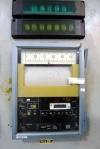
Operational reactivity reserve (OZR) chart recorder in the Unit 2 control room at Chernobyl. Handwritten note on the paper indicates its decommissioning in October of 1991, following the fire that ended Unit 2’s service life. The OZR quantity–essentially the number of full-worth control rods remaining in the reactor core–has great safety significance in RBMK reactors, and the inclusion of displays of this quantity for the operators in the control room was one of the improvements adopted after the Unit 4 accident in 1986.
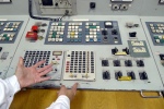
Controls for the No. 1 automatic power regulator on A Desk (reactor control engineer’s position) in Unit 2 at Chernobyl. This computerized regulator was one of two that were typically engaged under full-power routine operation.
Local Automatic Regulator (LAR) on A Desk (reactor control engineer’s position) in Unit 2 at Chernobyl. This regulator used in-core instrumentation to monitor and adjust the spatial neutron flux distribution at intermediate power levels during transition to or from full power.
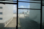
Two visitors investigate the notable radiation hot spot in the Unit 2 control room, in front of T Desk (turbine controls for Turbogenerator No. 4 are visible). The radiation seems to be streaming from above, perhaps from the steamwater compartment that directly overlies the control room. (Purely by coincidence, the men’s pose resembles the famous Soviet socialist-realism sculpture, “Worker and Kolkhoz Woman.”)
The two boiling water reactors at Peach Bottom Atomic Power Station are of the BWR/4 product line from General Electric and are housed in Mark I (“lightbulb”) containments. They share a common turbine building and a common control room. Electrical output is about 1200 MW each, leaving the station at a respectable 500 kV to feed the power-hungry metropolitan areas of the northeastern United States. Condenser waste heat is rejected to the Susquehanna River, supplemented during particularly hot weather by some small forced-draft cooling towers. Peach Bottom’s official name harkens back to 1958, when “atomic power” was a celebrated novelty, and construction began on a unique gas-cooled reactor at the Peach Bottom site. The GCR operated until 1974. Units 2 and 3 came on line that same year on a site on the right bank of the Susquehanna River just north of Unit 1.
Nuclear power plants have understandably committed unprecedented attention to safety and security in the last decade or so. An unfortunate side effect has been that those of us who don’t work in these facilities have scant resources to help wrap our heads around their scale, layout, equipment, and operations. With that in mind, I’m profoundly grateful to Exelon Corporation’s Peach Bottom staff, and in particular Jim Kovalchick, director of security, for allowing the comprehensive tour on which these photos were taken in April 2012.
To see pics with my descriptive captions, you must click “permalink” in the slideshow view after clicking the thumbnails below. Sorry that’s not obvious, but WordPress.com has gone all knuckle-head in the tech department this year. If you want to see the FULL SIZED photo: (1) click the thumbnail; (2) select “permalink”; (3) click the larger photo. Whew!
The control room in Unit 2 at Plant Vogtle, August 12, 2011, just before 5:00PM. Reactor controls at left, balance of plant on the right. The reactor is at full power. A routine maintenance and refuelling shutdown is planned for the Fall.
The American South is widely seen as the most viable US market for new nuclear power plants. Although the “nuclear renaissance” faces serious obstacles in the post-Fukushima world, if reactors are to be put on the grid then the South is almost certainly where it will happen first. Dominion’s North Anna plant, which I visited in 2009, plans to add an ESBWR. This August 12th and 15th I accompanied Atlanta fusion hobbyist Chad Ramey, his father, and friend Steven Shaw to two other southern nuclear nurseries. Plant Vogtle (pronounced “VO-gel” in local dialect) is an operating two-unit Westinghouse PWR plant of recent vintage that is adding two additional Westinghouse AP1000 reactors. Bellefonte Nuclear Generating Station, by marked contrast, is a 37-year-old never-completed Babcock and Wilcox PWR plant with two units, one of which TVA elected to complete by unanimous vote of its board on August 18.
Nuclear power plants are some of the most uptight and inaccessible places on the planet unless you work there, so I’m grateful to Mike McCracken at Plant Vogtle and to Chris Griffin at TVA for accommodating us. I’m especially indebted to Mike for all the photos from Plant Vogtle. (Unfortunately there is a strict no-photography policy in place at Bellefonte, so my gallery contains just two exterior shots. However, we visited the reactor vessel head, a steam generator, spent fuel pools, a cable spreader room, and the well-preserved ’70s-vintage control room, among many other parts of the plant.) Click any image below for a larger version with caption.
More interior photographs from the Chernobyl Nuclear Power Plant, this selection focusing on highlights of the Unit 1 control room and the building’s perhaps most distinguishing interior feature, its 600-meter-long “Gold Corridor.” Right-click any photo and select “open in new window” (or equivalent) for a larger version with my caption.
For this summer’s photos of the Unit 3 end of the power plant, see this post.
Our photos from ChNPP last year are displayed at this site.
The floor plan below is compiled from an official plant safety document and is meant to help illustrate the geography of the power plant on the +10-meter elevation, near Units 1-2.
+10-meter floor plan, Phase I, Chernobyl Nuclear Power Plant