They don’t give out spent nuclear fuel as a memento anymore. But on the tenth anniversary of the first nuclear reactor (the Chicago Pile) going critical, pile physicist Herbert L. Anderson was presented with this handsome “live block” of graphite and uranium metal fuel, piping hot and right out of the reactor core. With an estimated two millicuries of Cs-137 then distinguishing it from the natural uranium whence it was made, the unique artifact spent the next sixty years as part of Anderson’s home decor, a reminder of his pivotal role in one of the 20th century’s greatest triumphs in physics. Herb’s wife Betsy kindly gave it to me in 2014 with the hope that new understanding and appreciation would follow.
Now, having had nearly two years to get to know this artifact, I can share some preliminary findings about it–and a few lingering questions as well. I am grateful for ongoing partnerships with the University of Missouri and the Vinca Institute of Nuclear Sciences that are bringing new details to light about its metallurgy and history, and I am grateful for past assistance from the University of New Mexico here in Albuquerque. I am actively searching for ways to bring this piece of the first reactor to an appreciative public audience. So, dear reader, if you have suggestions or information that will help with either the technical understanding of the artifact, or its accommodation in a museum for the upcoming 75th anniversary of the Manhattan Project, please get in touch.
Part I: Basic physical description

This is a “live block” (meaning a piece of graphite with nuclear fuel installed in it), distinguished from the “dead blocks” of pure graphite that were interspersed or used as reflectors in the Chicago Pile. Several museums possess “dead blocks”; to my knowledge, these include the American Museum of Science and Energy (Oak Ridge), the Bradbury Science Museum (Los Alamos), the National Atomic Testing Museum (Las Vegas), and the National Museum of Nuclear Science and History (Albuquerque). My friend Kelly Michaels has an excellent photo set of these artifacts. Pieces of Chicago Pile fuel also survive independently; most notably, this piece once belonging to Alvin Weinberg. However, the Herb Anderson “live block” is unique, to my knowledge, in that it contains fuel and moderator together. The block’s measured dimensions, including fuel dimensions and those of the decorative housing, are available in a SolidWorks model to interested parties (please contact me).
The “T01” lot stamp appearing on the right face of the graphite block indicates that the graphite is AGOT made by the National Carbon Company, one of at least six types of graphite used to build the Pile. AGOT had the lowest neutron absorption of all of these types, so was preferred for the pile’s core region. About 2/3 of the CP-1 pile consisted of AGOT. This grade of nuclear graphite went on to be used in the Graphite Reactor at Oak Ridge and the plutonium production reactors at Hanford.
The fuel is unclad uranium metal in cylindrical elements that bear identifying stamp marks on the front faces. When I replaced the original cracked acrylic housing around the artifact, I was able to weigh the fuel elements directly. The left element weighed 2.564 kg, and the right one, 2.553 kg. The left element stamp reads “M230/L101/P2” while the right one reads “M170/L79/P1”. The significance of these marks remains unknown to me. I believe that if someone is able to assist in their interpretation, we might learn which of the three recorded contributing manufacturers of U metal produced this fuel. It should be noted that metal fuel was a small minority of the Chicago Pile fuel, amounting to just 5.4 metric tons; the vast majority of the fuel was pressed-oxide “pseudosphere” elements. Metal was made variously by Westinghouse, Metal Hydrides Corp., or the Ames Process.
Another question raised by this artifact is that it contains cylindrical metal fuel placed into chamfered recesses in the graphite designed for receiving “pseudosphere” oxide fuel. As such, the cylinders cannot remain centered or upright in the recesses without the assistance of some acrylic supports that may be seen in the x-ray image. I am quite sure that acrylic was not part of the original pile construction! One is tempted to question, then, whether this fuel-and-stringer combination is original. It could be that most graphite live blocks were machined for pseudosphere fuel, but when metal became available, the pseudosphere live blocks were used anyway (perhaps with graphite inserts serving the mechanical function of the acrylic supports, which begs the question of why the artifact contains acrylic instead; or perhaps without any supports, the fuel cylinders simply being dropped awkwardly into the recesses). A lack of detailed photos from the construction of CP-1 makes the question hard to answer.
Part II: Gamma spectrometric estimate of fuel burnup
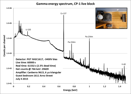
Mentioned earlier is the fact that this fuel contains cesium-137. In fact, the external radiation signatures are dominated by this long-lived fission product. Without a doubt, then, the fuel has been significantly exposed to reactor operation. By comparing count rates in the Pa-234m gamma peaks to that in the Cs-137 peak at 662 keV, we can determine the quantity of Cs-137 remaining in the fuel under the assumption that the Pa-234m is in equilibrium with its U-238 parent. This will motivate the estimation of fuel burnup range under various assumptions about the artifact’s history. I performed the requisite experiments with my PGT germanium detector and obtained the spectrum shown above, leading to an estimated activity of 540 microcuries of Cs-137 distributed throughout the total fuel at the time of measurement. Here are a few historical scenarios and the fuel burnup roughly corresponding to them:
- The fuel operates in CP-1 only (December 1942-February 1943): 163 kWd/MTU
- The fuel operates in CP-1 and its reconstruction in the Red Gate Woods (CP-2), and is removed from the operating reactor before being presented to Herb Anderson in November 1952 at the Tenth Anniversary celebration in Chicago: 132 kWd/MTU
- The fuel was removed from the pile (CP-2) when it was decommissioned in 1954, and somehow was then integrated into the artifact: 127 kWd/MTU
There are challenges with all three potential histories. The first is very unrealistic, given the known operating conditions of CP-1 in the brief months it was in use. Intermittently critical, with a peak power of ~200 W achieved on one day only, the burnup in the fuel attested by these calculations is many thousands of times greater than what is possible according to the conventional history of that Pile. The second scenario is supported by both the burnup calculation (even though I am aware of no formal operating records from CP-2) and the description given by Mrs. Anderson of how Herb got the item, but it leads to two big puzzles, firstly concerning how the fuel was removed from the reactor while the reactor was still in service, as the pile was not designed to be easily disassembled in the CP-2 instantiation; and secondly concerning the high activity levels of the discharged fuel when it must have been released from government custody to Anderson. The third explanation avoids the issue of taking apart the reactor just to obtain a souvenir as the reactor was disassembled during decommissioning; however, it is historically inconsistent with the story told by Mrs. Anderson. So what this gamma spectrometry measurement allows us to say with certainty is that the fuel was used in CP-2 (as well as the original pile, presumably). Beyond that, plenty of thought-provoking questions remain.
Part III: Neutron multiplication properties
It would seem there is no greater aspiration for a piece of the world’s first nuclear reactor than to return, momentarily, to the task originally undertaken with so much fanfare: multiplying neutrons in fission chain reactions. These three photos above show some multichannel-scaling apparatus to look at fission in the CP-1 block (set up in my kitchen, because this is a “cooking” project of sorts). We are going to examine the time correlation between neutron counts in a bank of two He-3 proportional counters next to our specimen. Both counter tubes and the specimen are reflected by polyethylene blocks to trap neutrons in the system as best we can. Highly-correlated counts point to fission “chains”, in which a fission event causatively leads to successive ones on a time scale controlled by the neutron transport properties of the specimen and surroundings. I’ll measure correlation by way of excess variance, or the Feynman Y-statistic: the difference between the measured variance-to-mean ratio of counts accumulated in a certain time window interval and unity (which corresponds to idealized, uncorrelated, Poisson-distributed counts). We’ll look at the CP-1 live block by itself and with a small additional neutron source present. We will also look at the neutron source alone, a lead brick, and the empty polyethylene cavity. Results and commentary below.
So what the fuck does this mean? Firstly, the CP-1 block by itself produces strongly time-correlated neutrons (purple data) on a measurement scale of about a millisecond or greater, while the little homemade AmBe neutron source is pretty much stochastic (red data). (Note, though, that the AmBe source is about five times stronger a neutron source than the block.) Putting the block in with the AmBe source slightly reduces the neutron count (~12%) versus the source alone, but produces excess correlation of nearly 30% of the block by itself, indicating the presence of induced fission. The high correlation in the block itself may be attributed to spontaneous fission (SF) as a minor decay mode of U-238, as well as a smaller contribution of spallation and fission induced by secondary cosmic rays. These neutron sources each produce a burst of neutrons, and are also closely coupled to successive induced fissions. The AmBe source, by contrast, is driven by radioactive decay: alpha particles slam into beryllium. Notice the curvature of the data in all cases: it rises as we lengthen the counting window. That is to say, there is more neutron correlation as the window gets longer. Neutrons take their time moving through materials, scattering, slowing down, and finally reaching the detector, and neutrons produced in coincidence will not register as such unless the window is long enough to account for their random meanderings through material. Finally, just to illustrate fission and other fission-like reactions in something other than uranium, I put a 20-pound lead brick in the counter. Now you may believe that lead is not a fissionable material, but under the right conditions–such as when a 500-MeV electron in the secondary cosmic ray spectrum hits it–the lead nucleus can split up by fission or by a somewhat similar process called spallation, cooking off a distribution of neutrons. And that is why we see highly-correlated neutrons (green data) being emitted by lead. Again note the upper right graph, though: lead is a very weak source of neutrons even though the ones that are emitted are highly time-correlated.


