I have been working on an ion source to support my next fusor and other small accelerator projects. Criteria for this source were that it had to be easy and inexpensive to fabricate myself with common components from reliable sources. My goals were to obtain high beam current and long service lifetime. I settled on an RF ion source concept with specific influences from Kiss and Koltay (1977). Tests of the prototype indicate stable sub-milliampere currents of deuterium ions over hours of operation. Cost (excluding RF and vacuum equipment): about $250.
_______________________________________________________________
 RF ion sources function by extracting ions from radiofrequency electrodeless discharges. These sources can deliver high-purity beams of atomic H+ ions. The vessel supporting such a discharge can be as simple as a glass test tube surrounded by an inductive coupling to the RF supply, as my design at left illustrates. The discharge is “enhanced” with the field from a strong magnet. Some builders attempt to exploit specific enhancement effects, e.g. electron cyclotron resonance or helicon phenomena. My goal with the magnet is just to promote generic electron trapping / heating, possibly by the above-mentioned modes if conditions are appropriate. Components, with suppliers’ names and stock numbers, are provided in the drawing.

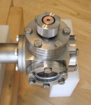
 Construction techniques involve drilling, lathe turning, silver brazing, and soft silver soldering. Photos at left show components of the source (most prominent are the extraction electrodes) during assembly on a ConFlat cube for testing.
Extraction of ions is accomplished by a strong DC electric field imposed between the negatively-biased “nozzle” on the 5/16″ tube and the grounded septum on the 1/2″ tube. I use up to -5 kV for extraction of ions. The extraction nozzle also throttles neutral gas flow from the discharge region into the vacuum chamber.
 RF power is supplied by an FAA-surplus AM-6155 power amplifier operating at 200 MHz. These amplifiers are a common hamfest bargain. Circuit details and modifications for the amateur radio hobby are easy to find online. To date I have not produced more than ~60W with this amplifier, driving it with signals below 1W. Beam current depends
  very strongly on RF power, and I plan to upgrade the driver for the AM-6155 to produce more. The top photo shows this amplifier producing power (lighting a mercury-vapor discharge), and the bottom photo shows the tube compartment of the amplifier modified for shunt feed of plate current.

 Inductive coupling of the 200-MHz power to the discharge plasma is effected with a single loop of heavy conductor that forms part of a resonant “L-match” circuit, providing an easy interface to 50-Ω cable. This is illustrated schematically at left. The right photo shows the ion source ready for testing, with the RF coupling loop visible along with other components including gas for the discharge (deuterium lecture bottle).
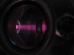
 Photos from operation. The top photo shows the RF deuterium discharge in a standard 19-mm (3/4″) Pyrex test tube, and below it a beam of extracted ions impinging on a graphite Faraday cup target. RF power is about 50W, extraction voltage -3 kV, and target at -10 kV. Background pressure has been raised into the millitorr range to enhance beam visibility. Extracted current is 0.25 milliampere.
  Bottom photo shows the exit aperture clearly, with deuteron beam passing through a ring electrode at -10 kV. Here the extraction voltage was -5 kV. It is not possible to accurately measure the beam current in this arrangement, but it is probably on the order of 0.5 mA. Not surprisingly, a few neutrons from 2H(d,n) fusion reactions can be detected with higher potentials on the ring cathode.
_______________________________________________________________
More information about this ion source
- Original description
- Discussion of AM-6155 RF supply
- A bit of operational data
- More recent modifications
- Improvement to the discharge bottle involving a little glassblowing


